
3D Point Cloud & Dimensional Analysis for Turbine Gears
-
in Techno Blog
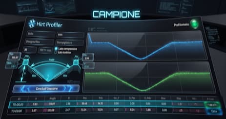
Turbine gears operate under conditions where a few microns of profile deviation can cascade into noise, vibration, and premature failure. LGE Engineering's 2D/3D laser scanning platform addresses this by capturing millions of points per second to build high-resolution digital twins of gear geometry, enabling sub-millimetre dimensional checks, complex geometry measurement, and surface defect detection without contact.
The measurement challenge for turbine gears is not simply one of accuracy. It is one of completeness. A gear is a three-dimensional object with involute flanks, root fillets, tip lands, and a repetitive tooth pattern that demands evaluation around the entire circumference.
Traditional contact methods—coordinate measuring machines and dedicated mechanical gauges—each solve half the problem. CMMs deliver accuracy but at a speed that makes 100% inspection impractical; dedicated gauges deliver speed but measure only the feature they were built for, requiring a new fixture for every gear variant.
LGE's 3DShaper series approaches the problem optically. The platform's profile sensors capture up to 3,200 points per profile at sampling rates reaching 4,000 profiles per second, with Z-axis resolution between 0.5 µm and 5 µm depending on the model selected. When mounted on a precision linear or rotary stage, the scanner acquires thousands of individual cross-sectional profiles as the gear rotates. Software assembles these into a dense 3D point cloud from which critical parameters are extracted: tooth thickness, pitch, tip and root diameters, runout, and involute profile deviation.
What the Point Cloud Enables
The output of this acquisition is not a pass/fail signal but a complete geometric representation. LGE lists dimensional extraction, volume measurement, and surface roughness as standard analytical outputs from the 3D point cloud generated by its scanners. For turbine gears, this means the measurement is not limited to the parameters the system was programmed to check. A gear that passes nominal dimensional tolerances but exhibits an unexpected surface irregularity—a handling mark, a grinding chatter pattern, or a localized root fillet deviation—remains visible in the data.
The platform's on-board processing includes built-in measurement tools for gap, step, angle, and radius, and the software supports real-time profile visualization and measurement tool configuration. The system is also AI-ready, with machine learning integration available for defect classification. This matters for turbine gear inspection because the defect classes that cause field failures are not always dimensional. Surface defects that evade a dimensional check may still compromise fatigue life.
Data Integrity in the Gear Shop Environment
A measurement system that performs in a laboratory but degrades near hobbing machines and grinding spindles is of limited value. LGE's gear measurement architecture addresses this through fiber optic data transmission between the scanner head and the processing unit, providing immunity to electromagnetic interference from nearby motors, drives, and induction heaters. The processing environment is a ruggedized industrial PC rather than a lab computer, running real-time filtering and feature extraction in milliseconds.
The sensor heads themselves carry IP67 protection and operate from 0°C to +45°C with cooling options available. Communication with plant infrastructure uses GigE Vision, Ethernet/IP, or PROFINET, allowing dimensional results to feed directly into production control systems rather than remaining isolated in an inspection station.
From Measurement to Process Control
The distinction between inspection and process control is the distinction between knowing a gear is bad and preventing the next one from being bad. LGE's software processes profiles against nominal CAD or master gear data and displays deviation values in microns alongside color-coded maps of profile error around the circumference. Trend charts support tool wear monitoring on hobs and shaper cutters. When a dimension drifts out of tolerance, the system can flag the part for rework or scrap, or feed data back to upstream machines for automatic offset adjustment.
For turbine gear manufacturing, this closed-loop capability is the operational payoff. A gear that is scrapped after heat treatment represents a significant value loss. A gear flagged at the hobbing stage for a profile deviation trend that has not yet exceeded tolerance represents an intervention opportunity.
Scope and Limitations
LGE's public documentation confirms turbine gears as a named application for its 3D point cloud and dimensional analysis platform, and confirms the sensor specifications cited above. The broader gear measurement discussion—involute evaluation, pitch analysis, runout—draws on LGE's published material on 2D laser scanning for gears, which describes the measurement principle and parameters in detail. It should be noted that the specific combination of turbine gear application labeling, sub-millimetre accuracy claims, and multi-million points per second acquisition appears in LGE's product literature without independent third-party validation in the available public record. Mills and gear shops evaluating the system should request application-specific demonstration data on their own gear geometries and surface finishes.
The proposition, however, is coherent with the platform architecture. A measurement system that captures the full surface, processes it in real time, and survives the gear shop environment addresses the three constraints—completeness, speed, and robustness—that have kept optical gear metrology from displacing contact methods in critical applications. For turbine gears, where failure consequences are high and inspection volumes justify investment in better data, that combination is the argument.